
Each SCSI channel on the
controller supports up to 14 drives. Drives can be of the Wide Ultra3 or Wide
Ultra2 type.
Each drive on a SCSI bus must have a unique ID value in the range 0 to 15
(except ID 7, which is reserved for controller use). This value is set
automatically on hot-pluggable drives in ProLiant servers and storage systems,
but values for other drives must be set manually.
À
Do not terminate the drives. HP and Compaq branded servers and
internal cabling provide the required termination of the SCSI bus.
À
Do not use drives of different capacity in the same array. The
excess capacity of larger drives cannot be used by the array and is wasted.
À
Do not use hot-pluggable drives on the same SCSI bus as
non-hot-pluggable drives.
Hard
drives that are currently supported by Smart Array controllers are listed at
www.hp.com/products/smartarray.
When a hard drive fails, all logical drives that are in the same array
will be affected. Each logical drive in an array may be using a different
fault-tolerance method, so each logical drive can be affected
differently.
À RAID 0 configurations cannot tolerate drive failure. If any physical drive in the array fails, all non-fault-tolerant (RAID 0) logical drives in the same array will also fail.
À RAID 1+0 configurations can tolerate multiple drive failures as long as no failed drives are mirrored to one another.
À RAID 5 configurations can tolerate one drive failure.
À RAID ADG configurations can tolerate simultaneous failure of two drives.
If more hard drives fail than the fault-tolerance method allows, fault
tolerance is compromised and the logical drive fails. In this case, all requests
from the operating system will be rejected with unrecoverable errors. The
ôCompromised Fault Toleranceö section discusses possible ways to recover from
this situation.
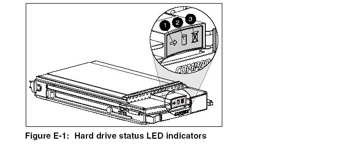
The LEDs on the front of each hard drive are visible through the front of the server or external storage unit. When a drive is configured as a part of an array and attached to a powered-up controller, the status of the drive can be determined from the illumination pattern of these LEDs
|
Table E-1: Proliant Hard Drive Status from
LED Illumination Pattern | |||
|
(1)
Activity |
(2)
Online |
(3)
Fault |
Meaning
|
|
On,
off, or flashing |
On
or off |
Flashing
|
A
predictive failure alert has been received for this drive. Replace the
drive as soon as possible. |
|
On,
off, or flashing |
On
|
Off
|
OK
to replace the drive online if the array is configured for fault tolerance
and all other drives in the array are online. The
drive is online and configured as part of an array.
|
|
On
|
Flashing
|
Off
|
Do
not remove the drive. Removing a drive during this process may terminate
the current operation and cause data loss. The
drive is rebuilding or undergoing capacity expansion.
|
|
On
|
Off
|
Off
|
Do
not remove the drive. Removing a drive during this process may cause data
loss. The
drive is being accessed, but (1) it is not configured as part of an array;
(2) it is a replacement drive and rebuild has not yet started; or (3) it
is spinning up during POST. |
|
Flashing
|
Flashing
|
Flashing
|
Do
not remove the drive. Removing a drive during this process can cause data
loss in non-fault-tolerant configurations. Either
(1) the drive is part of an array being selected by the Array
Configuration Utility; (2) the Options ROMPaq utility is upgrading the
drive firmware; or (3) Drive Identification has been selected in Insight
Manager. |
|
Off
|
Off
|
On
|
OK
to replace the drive online. The
drive has failed and has been placed offline. |
|
Off
|
Off
|
Off
|
OK
to replace the drive online if the array is configured for fault tolerance
and all other drives in the array are online. Either
(1) the drive is not configured as part of an array; (2) the drive is
configured as part of an array, but a powered-up controller is not
accessing the drive; or (3) the drive is configured as an online spare.
|
There are several other ways to recognize that a hard drive has
failed:
À
The amber LED lights up on the front of a storage system if failed drives
are inside. (Other problems such as fan failure, redundant power supply failure,
or over-temperature conditions will also cause this LED to light up.)
À
A Power-On Self-Test (POST) message lists failed drives whenever the
system is restarted, as long as the controller detects one or more good drives.
For troubleshooting information, refer to Appendix G, ôDiagnosing Array
Problems.ö
À
The Array Diagnostic Utility (ADU) lists all failed drives.
Also, Insight Manager can detect failed drives remotely across a network.
For additional information about hard drive problems, refer to the HP
Servers Troubleshooting Guide.
Compromised fault tolerance commonly occurs when more physical drives
have failed than the fault-tolerance method can endure. In this case, the
logical volume is failed and unrecoverable disk error messages are returned to
the host. Data loss is likely to occur.
An example of this situation is where one drive on an array fails while
another drive in the same array is still being rebuilt. If the array has no
online spare, any logical drives on the array that are configured with RAID 5
fault tolerance will fail.
Compromised fault tolerance may also be caused by non-drive problems,
such as temporary power loss to a storage system or a faulty cable. In such
cases, the physical drives do not need to be replaced. However, data may still
have been lost, especially if the system was busy at the time that the problem
occurred.
When fault tolerance has been compromised, inserting replacement drives
does not improve the condition of the logical volume. Instead, if your screen
displays unrecoverable error messages, try the following procedure to recover
data.
1.
Power down the entire system, and then power it back up. In some cases, a
marginal drive will work again for long enough to allow you to make copies of
important files.
2.
If a 1779 POST message is displayed, press the F2 key to re-enable the
logical volumes. Remember that data loss has probably occurred and any data on
the logical volume is suspect.
3.
Make copies of important data, if possible.
4.
Replace any failed drives.
5.
After the failed drives have been replaced, the fault tolerance may again
be compromised. If so, cycle the power again. If the 1779 POST message is
displayed, press the F2 key to re-enable the logical drives, recreate your
partitions, and restore all data from backup.
To minimize the risk of data loss due to compromised fault tolerance,
make frequent backups of all logical volumes.
Automatic data recovery is an automatic background process that rebuilds
data onto a spare or replacement drive when another drive in the array fails.
This process is also called rebuild.
If a drive in a fault-tolerant configuration is replaced while the system
power is off, a Power-On Self-Test (POST) message is displayed during the next
system startup. This message prompts you to press the F1 key to start automatic
data recovery. If automatic data recovery is not enabled, the logical volume
remains in a ready-to-recover condition and the same POST message is displayed
whenever the system is restarted.
When automatic data recovery has finished, the Online LED of the
replacement drive stops blinking and begins to glow
steadily.
In general, approximately 15 minutes is required to rebuild each
gigabyte. The actual rebuild time depends upon:
À
The level of rebuild priority that has been set for the logical drive.
For details, refer to, ôConfiguring an Array.ö Of the Smart Array Users
Guide .
À
The amount of I/O activity occurring during the rebuild operation
À
The disk drive speed
À
The number of drives in the array (for RAID 5 and RAID ADG)
For example, the rebuild time when using 9-GB Wide-Ultra hard drives in a
RAID 5 configuration varies from ten minutes per gigabyte (for three drives) to
20 minutes per gigabyte (for 14 drives).
If the Online LED of the replacement drive stops blinking during
automatic data recovery, there are three possible causes:
À
If the Online LED is glowing continuously, automatic data recovery was
successful and has finished.
À
If the amber failure LED is illuminated or other LEDs go out, the
replacement drive has failed and is producing unrecoverable disk errors. Remove
and replace the failed replacement drive.
À
If the automatic data recovery process has abnormally terminated, one
possible cause is a non-correctable read error on another physical drive. The
system may temporarily become operational if rebooted. In any case, locate the
faulty drive, replace it, and restore data from backup.
CAUTION: Sometimes, a drive that has previously been failed by the controller may seem to be operational after the system is power-cycled, or (for a hot-pluggable drive) after the drive has been removed and reinserted. However, continued use of such marginal drives may eventually result in data loss. Replace the marginal drive as soon as possible
There are several other factors to remember when replacing a hard drive:
À
Non-hot-pluggable drives should only be replaced while the system is
powered down.
À
Hot-pluggable drives can be removed and replaced at any time, whether the
host or storage system power is on or off.
À
When a hot-pluggable drive is inserted, all disk activity on the array
pauses while the new drive is spinning up (usually 20 seconds or so). If the
drive is inserted while power is on, in a fault-tolerant configuration, data
recovery onto the replacement drive begins automatically (indicated by the
blinking Online LED).
À
Replacement drives must have a capacity no less than that of the smallest
drive in the array. Drives of insufficient capacity will be failed immediately
by the controller before automatic data recovery can begin.
When
you set the SCSI ID jumpers manually, check the ID value to be sure that the
correct physical drive is being replaced. Set the same ID value on the
replacement drive to prevent SCSI ID conflicts.
CAUTION: In systems using external data storage, take care that the server is the first unit to be powered down and the last to be powered back up. Doing this ensures that the system will not erroneously mark the drives as failed
The rebuild operation takes several hours, even if the system is not busy
while the rebuild is in progress. System performance and fault tolerance are
both affected until the rebuild has finished. Therefore, replace drives during
low activity periods whenever possible. In addition, be sure that all logical
volumes on the same array as the drive being replaced have a current, valid
backup.
If another drive in the array fails while fault tolerance is unavailable
during rebuild, a fatal system error may occur. If this happens, all data on the
array is lost. In exceptional cases, however, failure of another drive need not
lead to a fatal system error. These exceptions
include:
À
Failure after activation of a spare drive
À
Failure of a drive that is not mirrored to any other failed drives (in a
RAID 1+0 configuration)
À
Failure of a second drive in a RAID ADG configuration
When a hard drive is replaced, the controller gathers fault-tolerance
data from the remaining drives in the array. This data is then used to rebuild
the missing data (originally on the failed drive) onto the replacement drive. If
more than one drive is removed at a time, the fault-tolerance data is
incomplete. The missing data cannot then be reconstructed and is likely to be
permanently lost.
To minimize the likelihood of fatal system errors, take these precautions
when removing failed drives:
À
Do not remove a degraded drive if any other member of the array is
offline (the Online LED is off). In this condition, no other drive in the array
can be removed without data loss.
o
There are some exceptions:
º
When RAID 1+0 is used, drives are mirrored in pairs. Several drives can
be in a failed condition simultaneously (and they can all be replaced
simultaneously) without data loss, as long as no two failed drives belong to the
same mirrored pair.
º
When RAID ADG is used, two drives can fail simultaneously (and be
replaced simultaneously) without data loss.
º
If an online spare has an unlit Online LED (it is offline), the degraded
drive can still be replaced.
À
Do not remove a second drive from an array until the
first failed or missing drive has been replaced and the rebuild process is
complete. (When the rebuild is complete, the Online LED on the front of the
drive stops blinking.)
o
There are some exceptions
º
In RAID ADG configurations, any two drives in the
array can be replaced simultaneously
º
In RAID 1+0 configurations, any drives that are not
mirrored to other removed or failed drives can be simultaneously replaced
offline without data loss
You can move drives to other ID positions on the same array controller.
You can also move a complete array from one controller to another (even if the
controllers are on different servers). However, if you combine arrays that were
on different controllers into one larger array on a single controller, the data
on the arrays is lost.
Before moving drives, these conditions must be met:
À
The move will not result in more than 14 physical drives per
channel.
À
No more than 32 logical volumes will be configured for a controller.
À
No drives are failed or missing.
À
The array is in its original configuration with no active spare drives.
À
Capacity expansion is not running.
À
Controller firmware is the latest version (recommended).
If moving an array, all drives in the array must be moved at the same
time.
IMPORTANT: There are
some restrictions on moving an array:
À
A drive array that has been moved from a battery-backed array controller
to one that is not battery-backed can no longer undergo RAID/stripe size
migration, array capacity expansion, or logical drive capacity extension.
À Do not move an array that is configured with RAID ADG to a controller that does not support RAID ADG. Only controllers that support RAID ADG can recognize a drive array that has this configuration
When the conditions have been met:
1.
Back up all data before removing any drives or changing configuration.
This step is required if you are moving data-containing drives from a controller
that is not battery backed.
2.
Power down the system.
3.
Move the drives.
4. Power up the system.
5. Restore the data from backup if necessary.
A 1724 POST message is displayed, indicating that drive positions were changed and the configuration was updated.
CAUTION: If a ôNot Configuredö POST message is displayed, power the system down immediately to avoid data loss, and then return the drives to their original locations.You can now check the new drive configuration by running ORCA or the
Array Configuration Utility. For details, refer ôConfiguring an Array.ö
You can increase the storage capacity on a system by swapping drives one at a time for higher capacity drives. This method is viable as long as a fault-tolerance method is running, and can be done even if there are no available drive bays.
CAUTION: Because a data rebuild takes about 15 minutes per gigabyte, your system is unprotected against drive failure for many hours, or even days, while the rebuild is in progress
To upgrade hard drive capacity:
1. Back up all data.
2. Replace any drive. The data on the new drive is re-created from redundant information on the remaining drives
3. When
data on the new drive has been rebuilt (the Activity LED is no longer
illuminated), repeat the previous step for the other drives in the array, one at
a time.
CAUTION: Do not replace any other drive until data rebuild on this drive is complete.
When all drives have been replaced, you can use the extra
capacity to create new logical drives or extend existing logical drives.
Array
capacity expansion is the addition of physical drives to an array and the
redistribution of the pre-existing logical drives over the enlarged array. Users
often incorrectly make synonymous the terms Expansion and Extension, thinking
that by added additional physical drives to an existing array, they will
simultaneously be adding space to there existing logical drive that is ôout of
spaceö. This notion is not correct. The addition does not effect the size of the
existing logical drives or partitions (C:, D:, etc.) but adds available space to
the array, logically visible as free, unformatted space, to the OS.
The expansion process is illustrated in Figure E-2, where the original array (containing data) is shown with a dashed border, and the newly added drives are shown unshaded (containing no data). The array controller adds the new drives to the array and redistributes the original logical drives over the enlarged array, one logical drive at a time. Each logical drive keeps the same fault-tolerance method in the enlarged array that it had in the smaller array.
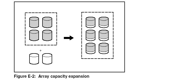
The unused
capacity on the enlarged array can now be used to create an additional logical
drive, with a different fault-tolerance setting if necessary.
Alternatively,
the unused capacity can be used to increase the size of one of the original
logical drives; this process is logical drive capacity extension. Another method
for carrying out logical drive capacity extension is to delete an existing
logical drive and then to add the freed capacity to another logical drive.
Capacity
expansion is carried out using one of the utilities described in, ôConfiguring
an Arrayö. For reconfiguration to occur online (that is, without shutting down
the operating system), the configuration utility must be running in the same
environment as the normal server applications. Also, online expansion is
possible only in systems that are using hot-pluggable drives.
Only ACU and
ACU 6.0 support capacity extension. Also, not all operating systems allow
extension to be carried out while the system is online. For details, refer to
Chapter 6 of your controller user guide, ôConfiguring an
Array.ö